The other system parameters are given in PID turn-table experiment post and will be used them in SI unit form in the simulation.

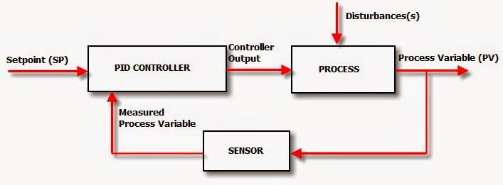
We will be using these paameters to implement the controller. After that we will report the step response characteristics for the simulated system.įrom out experiment we found that, the PID controller parameters are \(K_P = 2, T_d = 5e-4 min, T_i = 5e-5 min\). We are now ready to simulate the response of the same PID turn-table experiment for a unit step input. Percentage of Overshoot: Percentage difference between the maximum peak of the response and steady state response, relative to the steady state response. Settling time \((T_s)\): The time that the response signal would take to settle within 2% error relative to the steady-state response. Rise time \((T_r)\): The time that the response signal would take to reach to 90% from 10% of the steady-state response. There are three main characteristics of the step response. The figure below show the block diagram of the whole system with specified blocks representing relevant components. To derive the TF of the whole system, we need to first have the block diagram of the system incorporating the feedback PID loop. In order to perform theoretical analysis, we need to derive transfer function (TF) of the system. We calculated the potentiometer resistance value by following the working principle of non-inverting operational-amplifier (Op-Amp) as shown in the figure below. In order to achieve the gain=12V/0.52V in the feedback loop, we need to set the resistance of the potentiometer This has precisely been implemented in the feedback loop amplifier. Therefore, the tachometer output voltage needs to be amplified with a gain ratio of 12V/0.52V to infer the actual input voltage to the DC motor. On the other hand, motor’s speed is measured through the tachometer which produces 0.52V signal for 1000 RPM shaft speed. The DC motor rotates at 1000 RPM when connected to a 12V input signal with no-load condition. The turntable is controlled by a DC motor with a tachometer. The circuit diagram of the above physical circuit is as below. You can see the setup of the experiment below.

The interface between the digital controller and analog circuit is made through a data acquisition system (DAQ) from Texas Instruments. The objective of this experiment was to implementing an analog circuit to communicate a turntable and controlling its speed through a digitally implemented PID controller. We describe here the effectiveness of PID controller for a single-input-single-output (SISO) system using experiment.


 0 kommentar(er)
